-
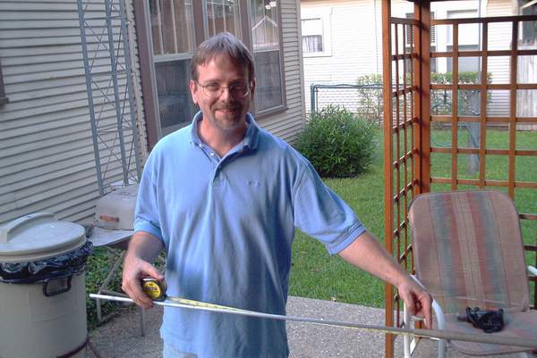
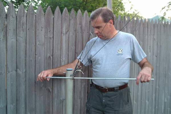
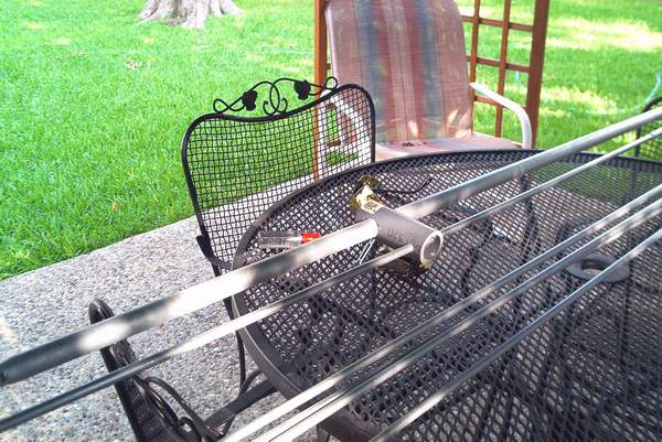
Ken Noblitt N5UA making initial measurements on the radiating element
-
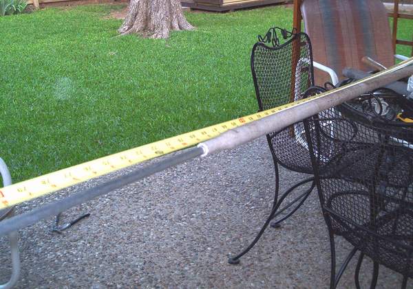
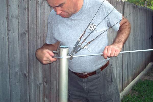
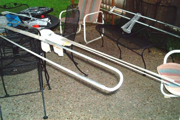
Additional measuring - showing detail of the new solid radiating element extension
-
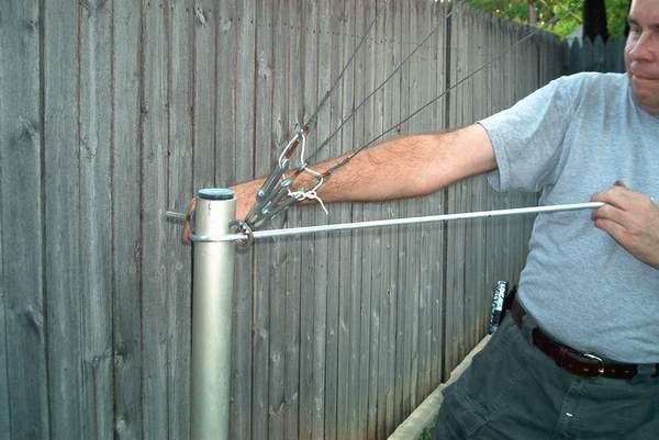
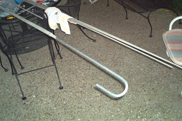
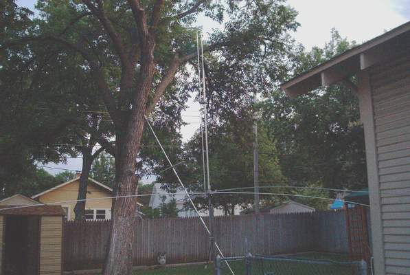
The new solid radiating element after bending and installed for a fit check
-
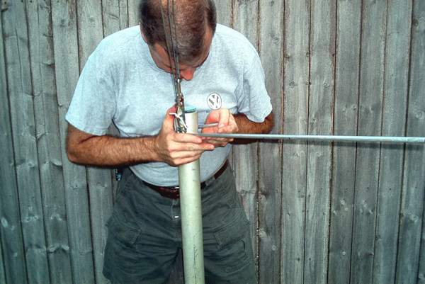
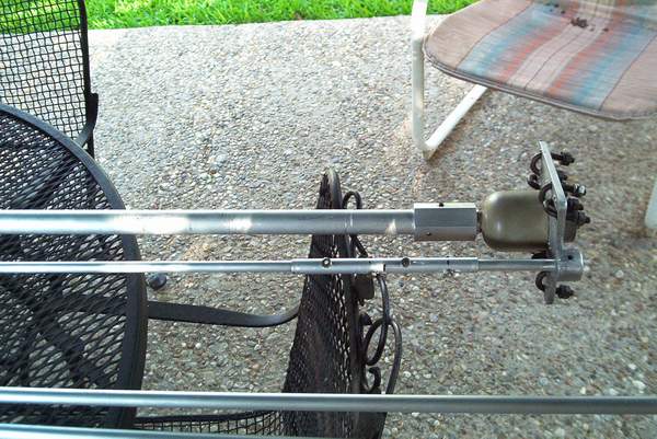
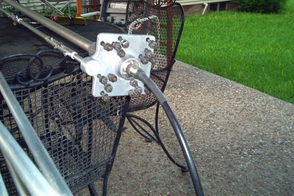
Sleeve installed for a fit check on new solid radiating element splice
-
Another sleeve for a different splice location after final mechanical fastening
-
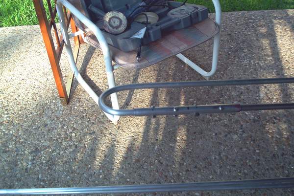
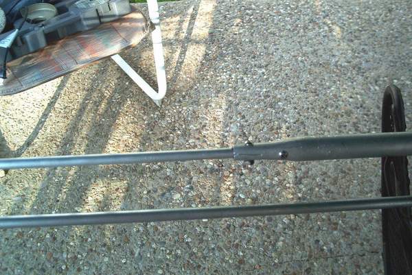
The splice between the new solid radiating element and the main radiating element tube
-
The radiating element spacer installed - it is made of outdoor grade PVC pipe
Final test data for the antenna after fine tuning of the ground radial lengths
VSWR measurements
29.0 MHz 1.5:1
29.56 MHz 1.1:1
30.0 MHz 1.25:1
For operation at 29.56 MHz, the length of the radiating
element to the ground radial base
should be 92 inches
and the length of the ground radials should be 128 inches.
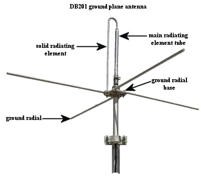
Modification of a DB201 ground plane antenna to 6 meters
For operation at 52.525 MHz, the length of the radiating
element to the ground radial base
should be 50.5 inches and the length of the ground radials should be 73
inches.
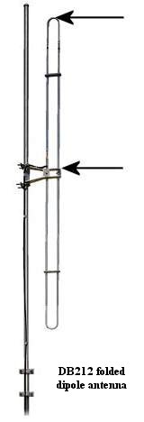
Modification of a DB212 folded dipole antenna to 6 and 10 meters
Here's the information to either shorten a lower than 50
MHz DB212 to 6M or to lengthen a higher
than 30 MHz DB212 to 10M:
10M (29.6 MHz) 94 inches
6M (52.525 MHz) 51 inches
Refer to the picture below of a DB212 antenna. The measurements above
are for the distance between the
2 arrows. Both the top half of the dipole and the bottom half of the
dipole should be to the same dimension.
These dimensions were determined by calculating the
approximate lengths and then fine tuning when the antenna
was mounted about 15 feet above the ground to it's lowest point on a
Rohn 25 tower. Note that these antennas
are designed to be mounted to the side of a tower or a pipe for proper
loading/tuning.
This page was last updated on 13 January, 2008 11:39:15 -0600 by webmaster xanaduu
All photos by Chuck Adams.
All contents copyright 1997
- 2008 by Charles P. Adams, Fort Worth, Texas USA.
